
StorCenter Installation
Introduction
|
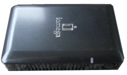
This document describes in depth how to prepare your Iomega StorCenter G2 for installing NetBSD/sandpoint. The three supported models are:
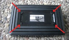
All models have 64 MB RAM and a PATA disk interface. Note that newer StorCenter models use an ARM CPU and are not supported. To install NetBSD/sandpoint you will have to open the case for getting access to the serial console. This is shown here for the Single Drive model. |
|
Accessing the serial interface
We need a serial console to get access to the firmware. That includes soldering a cable to the board and building (or buying) a serial adapter to convert from the StorCenter's TTL levels to RS232 levels.
Disassemble the StorCenter Single Drive
|
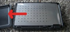
The Single Drive model is somewhat tricky to open. Move the cover by applying some force into the direction away from the interface bezel. It will eventually snap open. Then remove the metal shielding. Again, there are no screws. It is held in place by some brackets. Just pull it upwards and you will see the hard disk. |
|
|
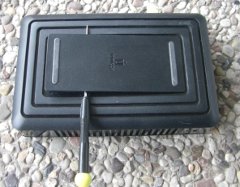
Do not try to access the screws, which are securing the disk drive, through the plastic vents. To be able to pull the metal case up we have to remove four screws at the bottom first, which are hidden behind a plastic plate. Pry open the plastic plate using a levering tool, like a screw driver. You will need some force to do that. |
|
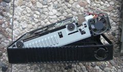
Remove the four screws at the bottom. Now you can easily pull the metal case out. |
|
|
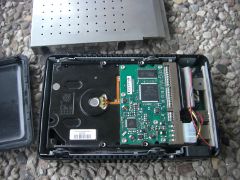
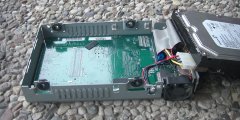
Remove the four screws which are securing the hard disk and unplug its connectors. Also remove the fan and the LED from the metal case. Now you can pull the mainboard out of the metal case, by moving it into the direction of the rear bezel. |
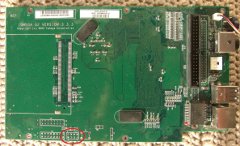
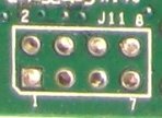
Locate the serial header
Look out for an unpopulated 8-pin header, called J11
(marked red on the picture to the left). The leftmost four pins can
be used for the serial interface. The pin assignments are shown
in the table.
|
|
|
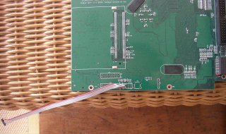
Attaching a serial cable
|
It is not recommended to solder a header onto |
|
Serial connection
The serial port on the StorCenter is using 3.3V TTL levels, which have to be converted into regular RS232 levels by a level shifter circuit. If you are not anxious using a soldering iron you find detailed instructions how to build such a converter here:
Make sure that the layout of the plug fits to the pinout of the StorCenter's serial header, as shown above.
Another option is to buy such a converter. There are solutions for a standard RS232 interface and for an USB interface. Look out for:
- RS232 level shifter / breakout board (MAX3232 based)
- USB to TLL serial level shifter / breakout board (FT232 based)
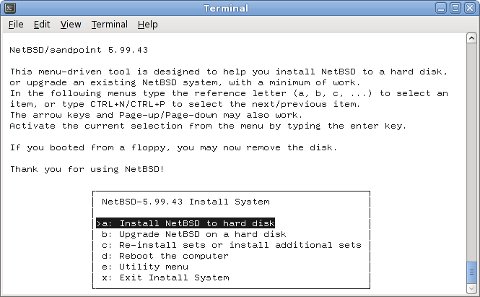
First installation
Accessing the Firmware
Provided the serial converter is installed and working correctly you should be able to connect to the firmware's serial console. Iomega is using U-Boot, the Universal Boot Loader.
Now you can connect with any terminal program to the StorCenter's
serial console. The easiest approach may be to use NetBSD's
tip(1) command to make a direct console
connection at 115200bps.
# tip -115200 console
Note that when using a serial connection via USB you may have to
make an entry for /dev/ttyU0 in
/etc/remote.
Immediately after switching your StorCenter on it will display the following information (output is from a Single Drive model) and gives you one second to stop autobooting.
U-Boot 1.0.0 (Sep  2 2005 - 14:49:11)

CPU:   MPC8241 Revision 1.4 at 199.999 MHz: 16 kB I-Cache 16 kB D-Cache
Board: StorCenter
PICR1 is now 00141b98
PICR2 is now 00040605
AMBOR is now c1
DRAM:  64 MB
FLASH:  8 MB
In:    serial
Out:   serial
Err:   serial
Net:   PCI device RTL8169#0: unknown chip version, assuming RTL-8169
PCI device: TxConfig = 0x0
RTL8169#0
Hit any key to stop autoboot:  0
altboot
The altboot(8) utility functions as a bridge between
the Iomega firmware and the NetBSD kernel startup environment.
NAS firmware often provides no means to boot a kernel from disk or
from the network and doesn't initialize all hardware correctly.
We will also use it to pass a bootinfo list to the kernel.
The altboot boot loader has to be loaded and started
using U-Boot. Usually there are three ways to invoke it:
- loadb to load a binary file via serial line in kermit mode
- tftpboot to load a binary file over the network with TFTP protocol
- start it from the flash memory
The last option is prefered once the installation is completed, but
obviously it is not possible for the first time boot.
Fortunately U-Boot has set up the network interface, which we can
use after configuring the ipaddr and serverip
environment variables:
IOMEGA=> setenv ipaddr 192.168.0.105
IOMEGA=> setenv serverip 192.168.0.5
IOMEGA=> saveenv
Saving Environment to Flash...
Un-Protected 1 sectors
Erasing Flash...
. done
Erased 1 sectors
Writing to Flash... done
Protected 1 sectors
Once you have set up TFTP and DHCP
(read below)
you can download altboot like this:
IOMEGA=> tftp 1000000 altboot.bin
TFTP from server 192.168.0.5; our IP address is 192.168.0.105
Filename 'altboot.bin'.
Load address: 0x1000000
Loading: ###############
done
Bytes transferred = 74732 (123ec hex)
Boot the INSTALL kernel with altboot
Now you can use altboot to launch the
netbsd-INSTALL kernel for installing NetBSD.
You may choose to load it with TFTP or from NFS. For TFTP you have
to enable tftpd(8) in
/etc/inetd.conf, and for NFS there is a
documentation at
The Network File System. But in both cases you
have to set up a DHCP server, which is explained in the
DHCP Howto
. An appropriate dhcpd.conf entry could
look like this:
        host storcenter {
                hardware ethernet 00:d0:b8:xx:xx:xx;
                fixed-address 192.168.0.105;
                next-server 192.168.0.5;
                option root-path "/export/storcenter/root";
        }
The root-path option is only needed when using NFS and
should match your exported NFS directory.
Uncompress netbsd-INSTALL.gz from the
NetBSD/sandpoint distribution and copy it into the NFS or TFTP
directory.
Then start the DHCP, NFS or TFTP server and boot the installation kernel
from the firmware either with
IOMEGA=> go 1000000 tftp:netbsd-INSTALL
or from NFS:
IOMEGA=> go 1000000 nfs:netbsd-INSTALL
Our bootloader configures the hardware, determines the IP address, loads the kernel via network and launches it:
## Starting application at 0x01000000 ...

>> NetBSD/sandpoint altboot, revision 1.8 (Wed Nov 23 21:51:40 CET 2011)
>> IOMEGA StorCenter G2, cpu 200 MHz, bus 100 MHz, 64MB SDRAM
channel 0 present
wd0: <ST3300822A> DMA LBA LBA48 286168 MB
wd0: no disklabel
MAC address 00:d0:b8:xx:xx:xx
100Mbps-FDX
Hit any key to enter interactive mode: 0
loading "netbsd-INSTALL" 5222228+112540=0x516b78
entry=0x90000, ssym=0x5a66f0, esym=0x5a6b78
Copyright (c) 1996, 1997, 1998, 1999, 2000, 2001, 2002, 2003, 2004, 2005,
    2006, 2007, 2008, 2009, 2010, 2011
    The NetBSD Foundation, Inc.  All rights reserved.
Copyright (c) 1982, 1986, 1989, 1991, 1993
    The Regents of the University of California.  All rights reserved.

NetBSD 5.99.59 (INSTALL) #10: Fri Dec 30 18:53:09 CET 2011
	frank@compaq.owl.de:/home/frank/netbsd/current/src/sys/arch/sandpoint/compile/obj/INSTALL
Model: iomega
total memory = 65536 KB
avail memory = 57904 KB
OpenPIC Version 1.2: Supports 1 CPUs and 26 interrupt sources.
mainbus0 (root)
cpu0 at mainbus0: 8245 (Revision 0.4), ID 0 (primary)
cpu0: HID0 0x90c000<DOZE,DPM,ICE,DCE>, powersave: 1
eumb0 at mainbus0
com0 at eumb0 unit 0: ns16550a, working fifo
com0: console
com0: interrupting at irq 40
ociic0 at eumb0
iic0 at ociic0: I2C bus
dsrtc0 at iic0 addr 0x68: DS1307 Real-time Clock/NVRAM
satmgr0 at eumb0 unit 1: button manager (iomega)
satmgr0: interrupting at irq 41
pci0 at mainbus0 bus 0
pchb0 at pci0 dev 0 function 0
pchb0: vendor 0x1057 product 0x0006 (rev. 0x14)
viaide0 at pci0 dev 13 function 0
viaide0: VIA Technologies VT6410 IDE controller
viaide0: using irq 17 for native-PCI interrupt
atabus0 at viaide0 channel 0
atabus1 at viaide0 channel 1
ohci0 at pci0 dev 14 function 0: vendor 0x1033 product 0x0035 (rev. 0x43)
ohci0: interrupting at irq 18
ohci0: OHCI version 1.0
usb0 at ohci0: USB revision 1.0
ohci1 at pci0 dev 14 function 1: vendor 0x1033 product 0x0035 (rev. 0x43)
ohci1: interrupting at irq 19
ohci1: OHCI version 1.0
usb1 at ohci1: USB revision 1.0
ehci0 at pci0 dev 14 function 2: vendor 0x1033 product 0x00e0 (rev. 0x04)
ehci0: interrupting at irq 20
ehci0: companion controllers, 3 ports each: ohci0 ohci1
usb2 at ehci0: USB revision 2.0
re0 at pci0 dev 15 function 0: RealTek 8169/8110 Gigabit Ethernet (rev. 0x10)
re0: interrupting at irq 16
re0: Ethernet address 00:d0:b8:xx:xx:xx
rgephy0 at re0 phy 7: RTL8169S/8110S/8211 1000BASE-T media interface, rev. 3
rgephy0: 10baseT, 10baseT-FDX, 100baseTX, 100baseTX-FDX, 1000baseT, 1000baseT-FDX, auto
biomask 1f000000 netmask 1f000000 ttymask 1f000000
uhub0 at usb0: vendor 0x1033 OHCI root hub, class 9/0, rev 1.00/1.00, addr 1
uhub1 at usb1: vendor 0x1033 OHCI root hub, class 9/0, rev 1.00/1.00, addr 1
uhub2 at usb2: vendor 0x1033 EHCI root hub, class 9/0, rev 2.00/1.00, addr 1
wd0 at atabus0 drive 0
wd0: <ST3300822A>
wd0: 279 GB, 581421 cyl, 16 head, 63 sec, 512 bytes/sect x 586072368 sectors
boot device: re0
root on md0a dumps on md0b
root file system type: ffs
WARNING: preposterous TOD clock time
WARNING: using filesystem time
WARNING: CHECK AND RESET THE DATE!
erase ^H, werase ^W, kill ^U, intr ^C, status ^T
Terminal type? [vt100]
Just follow the usual procedure to install a NetBSD system.
Post installation steps
After a successful installation you want to make the system boot
standalone when switched on, without the need for a serial console.
So you have to modify the bootcmd in U-Boot's environment
and write the altboot.bin binary to the Flash ROM.
To find a suitable place in the Flash ROM you can use the
flinfo command and look out for empty sectors
(E). On my StorCenter I have chosen
0xffe80000. Replace that in all the following
commands if you have chosen a different address.
Load altboot.bin into memory at
0x1000000 again, as explained above.
Then execute the following commands to write it to Flash ROM:
IOMEGA=> protect off ffe80000 ffe9ffff
Un-Protected 2 sectors
IOMEGA=> erase ffe80000 ffe9ffff

. done
Erased 2 sectors
IOMEGA=> cp.b 1000000 ffe80000 18000
Copy to Flash... done
IOMEGA=> protect on ffe80000 ffe9ffff
Protected 2 sectors
Finally adapt the bootcmd environment string to
autoboot altboot and start the
netbsd kernel (which is the default name) from
wd0 on each reboot:
IOMEGA=> setenv bootcmd cp.b ffe80000 1000000 18000\; go 1000000 wd0:
IOMEGA=> saveenv
Saving Environment to Flash...
Un-Protected 1 sectors
Erasing Flash...
. done
Erased 1 sectors
Writing to Flash... done
Protected 1 sectors
The \ is important for setenv not to
misinterpret the ; as the end of the command.
Have fun with your mini NetBSD server!
Back to NetBSD/sandpoint Port Page